VHDL記述例 - UARTによるシリアル通信
はじめに
本ページでは,調歩同期方式シリアル通信を行うためのUART (Universal Asynchronous Receiver Transmitter)のVHDL記述例を紹介します. UARTをFPGAに実装することにより,D-sub9ピンのシリアルケーブルやUSB-シリアル変換モジュールを経由して,PCとFPGAなどの間でRS-232C準拠のシリアル通信が実現できます.
下記の環境で動作を確認しておりますが,動作を保証するものではありません. ソースコードは自己責任の上でご利用ください.
| OS | Microsoft Windows 7 Professional x64 Service Pack 1 |
|---|---|
| Quartus II | Altera Quartus II 12.0sp2 Web Edition |
| ModelSim | Mentor Graphics ModelSim-Altera Starter Edition v10.0d Service Pack |
| FPGA Board | Terasic DE0 (Altera Cyclone III EP3C16F484C6N) |
VHDL記述例
はじめに
今回紹介するUARTのVHDL記述例(以降では,UARTモジュールと呼びます)は,下図に示すような構成になっています. 最上位モジュール「UART」は,その下にクロック生成モジュール「clk_generator」, シリアル送信モジュール「tx」およびシリアル受信モジュール「rx」を内包しています. UARTモジュールは,これら下位モジュールの入出力信号を結線しています.
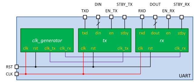
下表に各外部入出力信号の名称と機能をまとめました.入力クロックの周波数は50MHzです.
| Node Name | Direction | Description |
|---|---|---|
| CLK | Input | クロック入力.周波数は50MHzを想定 |
| RST | Input | リセット動作: 1,通常動作: 0 |
| TXD | Output | シリアル通信(送信) |
| RXD | Input | シリアル通信(受信) |
| DIN | Input | 送信データ入力 |
| DOUT | Output | 受信データ出力 |
| EN_TX | Input | 送信有効: 1,送信無効: 0 |
| EN_RX | Input | 受信有効: 1,受信無効: 0 |
| STBY_TX | Output | 待機中(初期状態): 1,送信中: 0 |
| STBY_RX | Output | 待機中(初期状態): 1,受信中または受信待機中: 0 |
下表に通信仕様をまとめました.
| ビットレート | 115200bps |
|---|---|
| データビット | 8bit |
| パリティビット | なし |
| ストップビット | 1bit |
| フロー制御 | なし |
最上位モジュール「UART」(UART.vhd)
最上位モジュール「UART」は,その下にクロック生成モジュール「clk_generator」, シリアル送信モジュール「tx」およびシリアル受信モジュール「rx」を内包しています. UARTモジュールは,これら下位モジュールの入出力信号を結線しています.
--------------------------------------------------------------------------------
-- UART Interface Unit
--  Start-stop synchronous communication (RS-232C)
--  115200bps, 8bit, no-parity, 1stop-bit
--------------------------------------------------------------------------------

library IEEE;
use IEEE.std_logic_1164.all;


-- top module
entity UART is port(
  CLK: in std_logic;
  RST: in std_logic;
  TXD: out std_logic;
  RXD: in std_logic;
  DIN: in std_logic_vector(7 downto 0);
  DOUT: out std_logic_vector(7 downto 0);
  EN_TX: in std_logic;
  EN_RX: in std_logic;
  STBY_TX: out std_logic;
  STBY_RX: out std_logic);
end UART;

architecture rtl of UART is
  signal CLK_TX: std_logic;
  signal CLK_RX: std_logic;

  component clk_generator port(
    clk: in std_logic;
    rst: in std_logic;
    clk_tx: out std_logic;
    clk_rx: out std_logic);
  end component;

  component tx port(
    clk: in std_logic;
    rst: in std_logic;
    clk_tx: in std_logic;
    txd: out std_logic;
    din: in std_logic_vector(7 downto 0);
    en: in std_logic;
    stby: out std_logic);
  end component;

  component rx port(
    clk: in std_logic;
    rst: in std_logic;
    clk_rx: in std_logic;
    rxd: in std_logic;
    dout: out std_logic_vector(7 downto 0);
    en: in std_logic;
    stby: out std_logic);
  end component;

  begin
    uclk_generator: clk_generator port map(
      clk => CLK,
      rst => RST,
      clk_tx => clk_tx,
      clk_rx => clk_rx);

    utx: tx port map(
      clk => CLK,
      rst => RST,
      clk_tx => clk_tx,
      txd => TXD,
      din => DIN,
      en => EN_TX,
      stby => STBY_TX);

    urx: rx port map(
      clk => CLK,
      rst => RST,
      clk_rx => clk_rx,
      rxd => RXD,
      dout => DOUT,
      en => EN_RX,
      stby=> STBY_RX);

end rtl;
クロック生成モジュール「clk_generator」(clk_generator.vhd)
クロック生成モジュール「clk_generator」は,シリアル通信に必要なクロックを生成し,シリアル送信モジュールおよびシリアル受信モジュールに供給します.
library IEEE;
use IEEE.std_logic_1164.all;
use IEEE.std_logic_unsigned.all;


-- clock generator module
entity clk_generator is port(
  clk: in std_logic;
  rst: in std_logic;
  clk_tx: out std_logic;
  clk_rx: out std_logic);
end clk_generator;

architecture rtl of clk_generator is
  -- (1 / 115200bps) / (1 / 50MHz) = 434
  signal cnt_tx: integer range 0 to 433;
  -- (1 / 115200bps) / (1 / 50MHz) / 16 = 27
  signal cnt_rx: integer range 0 to 26;

  begin
    clk_tx <= '1' when(cnt_tx = 433) else '0';
    process(clk, rst) begin
      if(rst = '1') then
        cnt_tx <= 0;
      elsif(clk'event and clk = '1') then
        if(cnt_tx = 433) then
          cnt_tx <= 0;
        else
          cnt_tx <= cnt_tx + 1;
        end if;
      end if;
    end process;

    clk_rx <= '1' when(cnt_rx = 26) else '0';
    process(clk, rst) begin
      if(rst = '1') then
        cnt_rx <= 0;
      elsif(clk'event and clk = '1') then
        if(cnt_rx = 26) then
          cnt_rx<= 0;
        else
          cnt_rx <= cnt_rx + 1;
        end if;
      end if;
    end process;

end rtl;
シリアル送信モジュール「tx」(tx.vhd)
シリアル送信モジュール「tx」は,シリアル通信における送信機能を提供します.
library IEEE;
use IEEE.std_logic_1164.all;
use IEEE.std_logic_unsigned.all;


-- transmitter module
entity tx is port(
  clk: in std_logic;
  rst: in std_logic;
  clk_tx: in std_logic;
  txd: out std_logic;
  din: in std_logic_vector(7 downto 0);
  en: in std_logic;
  stby: out std_logic);
end tx;

architecture rtl of tx is
  signal en_tmp: std_logic;
  signal cnt_bit: integer range 0 to 9;
  signal buf: std_logic_vector(7 downto 0);

  begin
    process(clk, rst) begin
      if(rst = '1') then
        txd <= '1';
        en_tmp <= '0';
        stby <= '1';
        cnt_bit <=  0;
        buf <= (others => '0');
      elsif(clk'event and clk = '1') then
        if(en = '1') then
          en_tmp <= '1';
          stby <= '0';
          buf <= din;
        elsif(clk_tx = '1' and en_tmp = '1') then
          case cnt_bit is
            when 0 =>
              txd <= '0';
              cnt_bit <= cnt_bit + 1;
            when 1 | 2 | 3 | 4 | 5 | 6 | 7 | 8 =>
              txd <= buf(0);
              buf <= '1' & buf(7 downto 1);
              cnt_bit <= cnt_bit + 1;
            when others =>
              txd <= '1';
              en_tmp <= '0';
              stby <= '1';
              cnt_bit <= 0;
          end case;
        end if;
      end if;
    end process;

end rtl;
シリアル受信モジュール「rx」(rx.vhd)
シリアル受信モジュール「rx」は,シリアル通信における受信機能を提供します.
library IEEE;
use IEEE.std_logic_1164.all;
use IEEE.std_logic_unsigned.all;


-- receiver module
entity rx is port(
  clk: in std_logic;
  rst: in std_logic;
  clk_rx: in std_logic;
  rxd: in std_logic;
  dout: out std_logic_vector(7 downto 0);
  en: in std_logic;
  stby: out std_logic);
end rx;

architecture rtl of rx is
  type state_type is (idle, detect, proc, stopbit);
  signal state: state_type;
  signal dout_reg: std_logic_vector(7 downto 0);
  signal en_tmp: std_logic;
  signal cnt_bitnum: integer range 0 to 7;
  signal cnt_bitwidth: integer range 0 to 15;
  signal buf: std_logic;

  begin
    dout <= dout_reg;

    process(clk, rst) begin
      if(rst ='1') then
        buf <= '0';
      elsif(clk'event and clk = '1') then
        buf <= rxd;
      end if;
    end process;

    process(clk, rst) begin
      if(rst ='1') then
        en_tmp <= '0';
        stby <= '1';
        dout_reg <= (others => '0');
        cnt_bitnum <= 0;
        cnt_bitwidth <= 0;
        state <= idle;
      elsif(clk'event and clk = '1') then
        if(en = '1') then
          en_tmp <= '1';
          stby <= '0';
        end if;
        if(en_tmp = '1') then
          case state is
            when idle =>
              if(buf = '0') then
                cnt_bitnum <= 0;
                cnt_bitwidth <= 0;
                state <= detect;
              else
                state <= state;
              end if;
            when detect =>
              if(clk_rx = '1') then
                if(cnt_bitwidth = 7) then
                  cnt_bitwidth <= 0;
                  state <= proc;
                else
                  cnt_bitwidth <= cnt_bitwidth + 1;
                  state <= state;
                end if;
              else
                state <= state;
              end if;
            when proc =>
              if(clk_rx = '1') then
                if(cnt_bitwidth = 15) then
                  if(cnt_bitnum = 7) then
                    cnt_bitnum <= 0;
                    state <= stopbit;
                  else
                    cnt_bitnum <= cnt_bitnum + 1;
                    state <= state;
                  end if;
                  dout_reg <= rxd & dout_reg(7 downto 1);
                  cnt_bitwidth <= 0;
                else
                  cnt_bitwidth <= cnt_bitwidth + 1;
                  state <= state;
                end if;
              else
                state <= state;
              end if;
            when stopbit =>
              if(clk_rx = '1') then
                if(cnt_bitwidth = 15) then
                  en_tmp <= en;
                  state <= idle;
                else
                  cnt_bitwidth <= cnt_bitwidth + 1;
                  state <= state;
                end if;
              else
                state <= state;
              end if;
            when others =>
              en_tmp <= '0';
              state <= idle;
          end case;
        elsif(en = '0' and en_tmp = '0') then
          stby <= '1';
        end if;
      end if;
    end process;

end rtl;
テストベンチとRTLシミュレーション
テストベンチ記述例
以下は,UARTモジュール用のテストベンチ記述例(tb_UART.vhd)です. テストベンチ記述,Quartus IIおよびModelSimを用いたRTLシミュレーションの方法については,加算器のRTLシミュレーションが参考になると思います.
library IEEE;
use IEEE.std_logic_1164.all;


entity tb_UART is
end tb_UART;

architecture rtl of tb_UART is
  signal CLK: std_logic;
  signal RST: std_logic;
  signal TXD: std_logic;
  signal RXD: std_logic;
  signal DIN: std_logic_vector(7 downto 0);
  signal DOUT: std_logic_vector(7 downto 0);
  signal EN_TX: std_logic;
  signal EN_RX: std_logic;
  signal STBY_TX: std_logic;
  signal STBY_RX: std_logic;

  -- global clock period
  constant CP: time := 20 ns;
  -- bit rate (1 / 115200bps)
  constant BR: time := 8680 ns;

  component UART port(
    CLK: in std_logic;
    RST: in std_logic;
    TXD: out std_logic;
    RXD: in std_logic;
    DIN: in std_logic_vector(7 downto 0);
    DOUT: out std_logic_vector(7 downto 0);
    EN_TX: in std_logic;
    EN_RX: in std_logic;
    STBY_TX: out std_logic;
    STBY_RX: out std_logic);
  end component;

  begin
    uUART: UART port map(
      CLK => CLK,
      RST => RST,
      TXD => TXD,
      RXD => RXD,
      DIN => DIN,
      DOUT => DOUT,
      EN_TX => EN_TX,
      EN_RX => EN_RX,
      STBY_TX => STBY_TX,
      STBY_RX => STBY_RX);

  -- clock signal
  process begin
    CLK <= '0';
    wait for CP / 2;
    CLK <= '1';
    wait for CP / 2;
  end process;

  process begin
    RST <= '1'; RXD <= '1'; DIN <= x"ff"; EN_TX <= '0'; EN_RX <= '0';
    wait for CP; RST <= '0';

    wait for CP; DIN <= x"65";
    wait for CP; EN_TX <= '1';
    wait for CP; EN_TX <= '0';

    wait for (16 * BR); EN_RX <= '1';
    wait for CP; EN_RX <= '0';

    wait for BR; RXD <= '0'; -- start-bit
    wait for BR; RXD <= '1'; -- data-bit 8'hc5
    wait for BR; RXD <= '0';
    wait for BR; RXD <= '1';
    wait for BR; RXD <= '0';
    wait for BR; RXD <= '0';
    wait for BR; RXD <= '0';
    wait for BR; RXD <= '1';
    wait for BR; RXD <= '1';
    wait for BR; RXD <= '1'; -- stop-bit

    wait for (2 * BR); EN_RX <= '1';
    wait for CP; EN_RX <= '0';

    wait for BR; RXD <= '0'; -- start-bit
    wait for BR; RXD <= '0'; -- data-bit 8'hf0
    wait for BR; RXD <= '0';
    wait for BR; RXD <= '0';
    wait for BR; RXD <= '0';
    wait for BR; RXD <= '1';
    wait for BR; RXD <= '1';
    wait for BR; RXD <= '1';
    wait for BR; RXD <= '1';
    wait for BR; RXD <= '1'; -- stop-bit

    wait for (4 * BR); RST <= '1';

    assert false report "Simulation End." severity failure;
  end process;

end rtl;
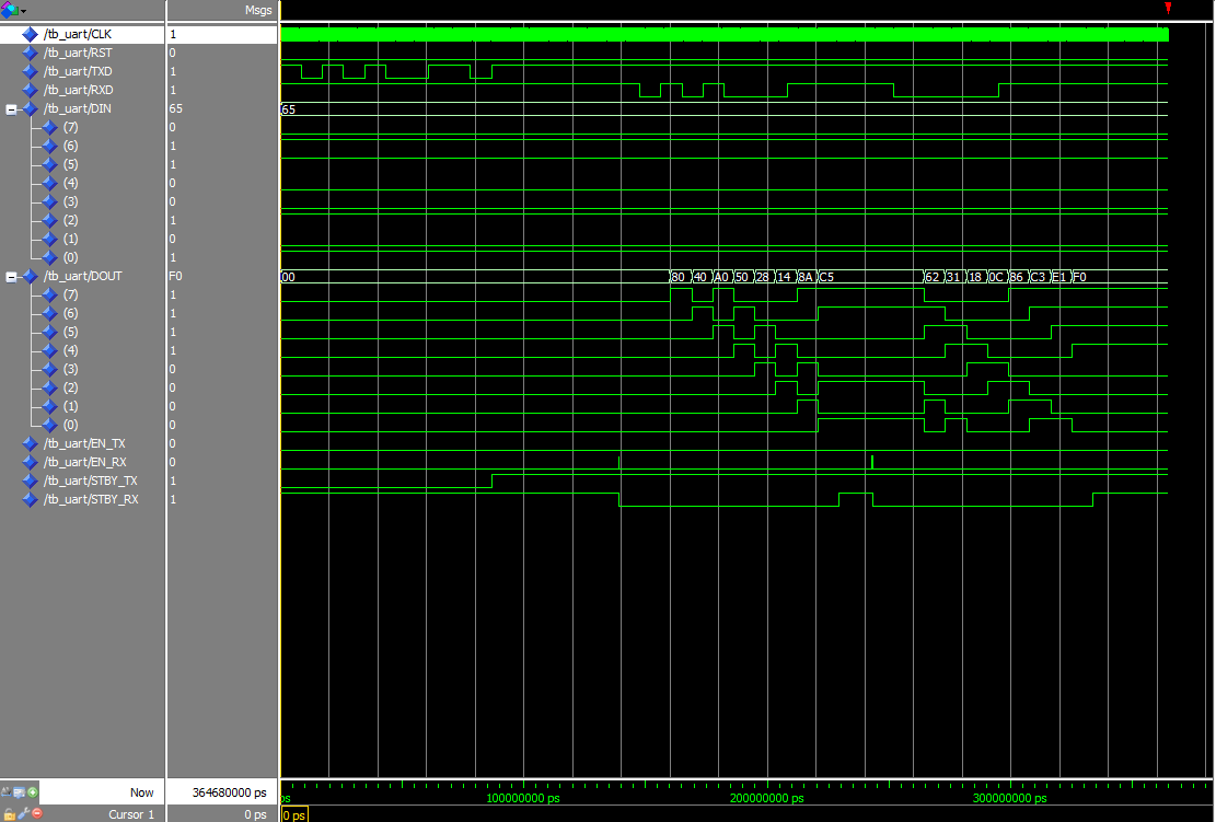
RTLシミュレーション結果
下図に,上記のテストベンチ記述例を使用したRTLシミュレーションの結果を示します.
Terasic DE0に,UARTによるシリアル通信を実装するためには
Terasic DE0にはD-sub9端子が実装されておらず,シリアル通信を行うためには, シリアルケーブルの作成やUSB-シリアル変換モジュールの購入などが必要となります. 下記にこれらの実装例をまとめましたので,ご一読ください.